Jagran Josh
4.1 INTRODUCTION
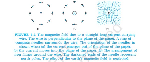
Moving charges or currents produce a magnetic field in the surrounding space.
4.2 MAGNETIC FORCE
4.2.1 Sources and fields
The magnetic field of several sources is the vector addition of magnetic field of each individual source.
4.2.2 Magnetic Field, Lorentz Force
If there is a point charge q (moving with a velocity v and, located at r at a given time t) in presence of both the electric field E (r) and the magnetic field B (r). The force on an electric charge q due to both of them can be written as:
F = q [ E (r) + v × B (r)]
Lorentz force F = Felectric +Fmagnetic
Features of Lorentz force
(i) It depends on q, v and B (charge of the particle, the velocity and the magnetic field). Force on a negative charge is opposite to that on a positive charge.
(ii) The magnetic force q [ v × B ] includes a vector product of velocity and magnetic field. The vector product makes the force due to magnetic field vanish (become zero) if velocity and magnetic field are parallel or anti-parallel. The force acts in a (sideways) direction perpendicular to both the velocity and the magnetic field. Its direction is given by the screw rule or right hand rule for vector (or cross) product.
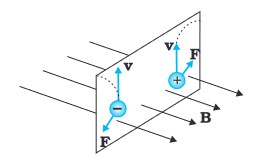
(iii) The magnetic force is zero if charge is not moving (as then |v|= 0). Only a moving charge feels the magnetic force.
Dimensionally, Magnitude of Magnetic field = [B] = [F/qv]
The earth’s magnetic field is about 3.6 × 10⁻⁵ T.
4.2.3 Magnetic force on a current-carrying conductor
In the presence of an external magnetic field B, the force on mobile charge carriers is:
F = (nlA)qvd x B
where q is the value of the charge on a carrier.
vd= average drift velocity
A = cross sectional area
l = length
F = (nlA)qvd x B can also be written as
F = [(nq vd )l A] × B = [ jAl ] x B
= Il x B
4.3 MOTION IN A MAGNETIC FIELD
During motion of a charge in a magnetic field, the magnetic force is perpendicular to the velocity of the particle. So no work is done and no change in the magnitude of the velocity is produced (though the direction of momentum may be changed).
4.4 MAGNETIC FIELD DUE TO A CURRENT ELEMENT, BIOT-SAVART LAW
According to Biot-Savart’s law, the magnitude of the magnetic field dB is proportional to the current I, the element length |dl|, and inversely proportional to the square of the distance r. Its direction* is perpendicular to the plane containing dl and r.

The Biot-Savart law for the magnetic field has certain similarities and differences with the Coulomb’s law for the electrostatic field:
(i) Both are long range, since both depend inversely on the square of distance from the source to the point of interest. The principle of superposition applies to both fields.
(ii) The electrostatic field is produced by a scalar source, namely, the electric charge. The magnetic field is produced by a vector source I dl.
(iii) The electrostatic field is along the displacement vector joining the source and the field point. The magnetic field is perpendicular to the plane containing the displacement vector r and the current element I dl.
(iv) There is an angle dependence in the Biot-Savart law which is not present in the electrostatic case. In Fig. 4.7, the magnetic field at any point in the direction of dl (the dashed line) is zero. Along this line,
q = 0, sin
q = 0 and
|dB| = 0.
Relation between the permittivity of free space; the permeability of free space; and the speed of light in vacuum:

4.5 MAGNETIC FIELD ON THE AXIS OF A CIRCULAR CURRENT LOOP
In a circular loop carrying a steady current I, placed in the y-z plane with its centre at the origin O, x-axis being the axis of the loop, having radius R, and x being the distance of P from the centre O of the loop:

The magnetic field at P due to entire circular loop is:

Right Hand Thumb Rule to Find the Direction of Magnetic Field:
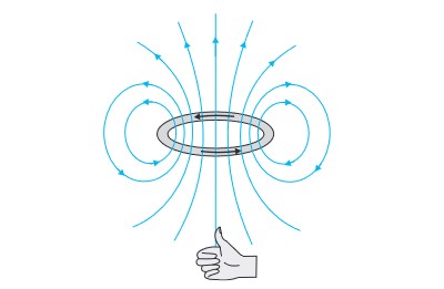
Curl the palm of your right hand around the circular wire with the fingers pointing in the direction of the current. The right-hand thumb gives the direction of the magnetic field.
4.6 AMPERE’S CIRCUITAL LAW
Ampere’s law is to Biot-Savart law, what Gauss’s law is to Coulomb’s law.
![]()
4.7 THE SOLENOID
![]()
In a long solenoid, net magnetic field is the vector sum of the fields due to all the turns.
4.8 FORCE BETWEEN TWO PARALLEL CURRENTS, THE AMPERE


![]()
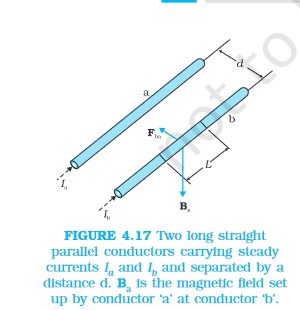
Parallel currents attract, and anti-parallel currents repel.
4.9 TORQUE ON CURRENT LOOP, MAGNETIC DIPOLE
4.9.1 Torque on a rectangular current loop in a uniform magnetic field
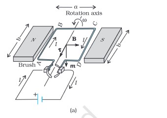
A rectangular loop carrying a steady current I and placed in a uniform magnetic field experiences a torque. It does not experience a net force. This behaviour is analogous to that of an electric dipole in a uniform electric field.
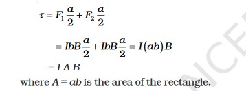
When the plane of the loop, is not along the magnetic field, but makes an angle with it. We take the angle between the field and the normal to the coil to be angle Theta
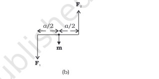
The magnitude of the torque on the loop is,

If the loop has N closely wound turns, the expression for torque m = NIA
4.9.2 Circular current loop as a magnetic dipole

4.10 THE MOVING COIL GALVANOMETER

The moving coil galvanometer (MCG) consists of a coil, with many turns, free to rotate about a fixed axis in a uniform radial magnetic field. There is a cylindrical soft iron core which not only makes the field radial but also increases the strength of the magnetic field. When a current flows through the coil, a torque acts on it. This torque is given by
t = NI AB
Deflection = ![]()
Uses of galvanometer:
It can be used as a detector to check if a current is flowing in the circuit. We have come across this usage in the Wheatstone’s bridge arrangement.
In this usage, the neutral position of the pointer (when no current is flowing through the galvanometer) is in the middle of the scale and not at the left end.
Depending on the direction of the current, the pointer’s deflection is either to the right or the left.
The galvanometer cannot be used as an ammeter to measure the value of the current in a given circuit.
This is because:
(i) Galvanometer is a very sensitive device, it gives a full- scale deflection for a current of the order of mA.
(ii) For measuring currents, the galvanometer has to be connected in series, and as it has a large resistance, this will change the value of the current in the circuit.
A moving coil galvanometer can be converted into a voltmeter by introducing a resistance of a large value in series.
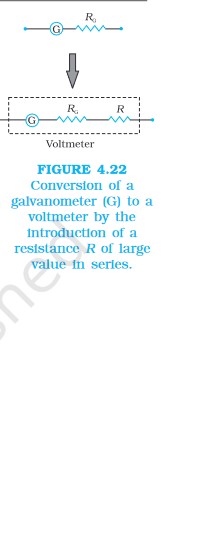
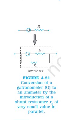
A moving coil galvanometer can be converted into a ammeter by introducing a shunt resistance rs, of small value in parallel.
#Moving #Charges #Magnetism #Class #Notes #CBSE #12th #Physics #Chapter #Download #PDF
